

Professor Helix says: "I can help you with that!"
Shaft Type: Supportworks generally recommends hollow round shaft products for pile applications resisting compression or combined compression/tension loads and square bar products for anchor and tieback applications resisting tension loads only. Square bar products may be considered to resist axial, concentric compression loads when adequate lateral resistance is provided by the soil. Square bar products are also generally used in Helicast pile design since the shaft and couplers above the lead section are encased in a grout column. Refer to the latest version of Supportworks' Technical Manual for further discussion of round versus square bar products.
| Shaft | Description | Torque Correlated Ultimate Capacity | Shaft Maximum Allowable Strength (ASD) (Pn/Ω) |
|||||||
|---|---|---|---|---|---|---|---|---|---|---|
| Compression | Tension | |||||||||
Torque Correlation Factor |
Shaft Torsional Rating |
Ultimate Soil Capacity |
Plain |
Corroded Plain |
Corroded Galvanized |
Plain |
Corroded Plain |
Corroded Galvanized |
||
| Kt | T | Qu | ||||||||
| (ft-1) | (ft-lb) | (kips) | (kips) | (kips) | (kips) | (kips) | (kips) | (kips) | ||
| HA150 | 1-1/2" Round Corner Solid Square Bar | 10 | 6,500 | 65.0 | 29.8 | 27.0 | 27.1 | 29.8 | 27.0 | 27.1 |
| HA175 | 1-3/4" Round Corner Solid Square Bar | 10 | 10,000 | 100.0 | 59.6 | 54.1 | 54.2 | 59.6 | 54.1 | 54.2 |
| HP237 | 2-3/8" O.D. Hollow Round Shaft x 0.154 Wall | 10 | 2,500 | 25.0 | 35.1 | 26.3 | 32.6 | 19.3 | 13.6 | 16.9 |
| HP287 | 2-7/8" O.D. Hollow Round Shaft x 0.203 Wall | 9 | 5,600 | 50.4 | 55.8 | 45.2 | 52.9 | 30.6 | 23.6 | 27.6 |
| HP288 | 2-7/8" O.D. Hollow Round Shaft x 0.276 Wall | 9 | 7,900 | 71.1 | 74.0 | 63.6 | 71.1 | 41.6 | 34.1 | 38.1 |
| HP350 | 3-1/2" O.D. Hollow Round Shaft x 0.340 Wall | 7 | 17,500 | 122.5 | 118.5 | 105.0 | 114.8 | 73.9 | 62.7 | 69.0 |
| HP450 | 4-1/2" O.D. Hollow Round Shaft x 0.337 Wall | 5.5 | 22,000 | 121.0 | 123.3 | 109.1 | 119.3 | 59.1 | 50.8 | 56.7 |
Head Depth: The pile head depth is the vertical distance of the top of pile relative to the upper soil layer surface. A positive value indicates a pile head below the upper soil layer surface, which may be representative of situations where piles are located below grade and within shallow pile caps or grade beams. The Head Depth feature is not intended to model deep, expansive excavations where overburden soils and stresses are removed from a granular soil profile. Instead, the User should modify the soil profile inputs to be representative of long-term conditions, including the presence or absence of overburden soils. A negative Head Depth value indicates a top of pile above the upper soil layer surface, which may represent elevated supports for boardwalks, billboards, solar panels, etc. Reminder: a buckling analysis should be considered when sections of (compression) piles extend through fluid soils, water or air.
Batter Angle: Helical piles are occasionally installed at a batter to resist lateral loads or to provide a center to center pile separation at the helix plate depth of at least three times the diameter of the largest helix. An input value of “0” would define a vertical pile to be installed without a batter angle. Input values for installation angles must be between 0 and 90 degrees.
Tip Depth: Bottom of pile determined by the program from the Head Depth, Batter Angle and Pile Length. User cannot override this field.
Helix Diameter: Supportworks offers true helix-shaped plates with diameters ranging from 6 to 16 inches. Plate spacing along the shaft is three times the diameter of the lower helix. Helix diameters generally increase from the pile tip up the shaft; e.g., 8-10, 10-12, 12-14, 8-10-12, 10-12-14, 10-12-14-16, etc. Common exceptions to this rule may include 10-12-14-14, 10-12-14-14-14, or 10-12-14-16-16 helix configurations. Selecting helix plates that decrease in size from the pile tip is not recommended and the program will instruct you that “Diameter must be non-decreasing” to prevent that condition. Project conditions may dictate that a consistent, maximum plate size must be used, resulting in a helix plate configuration such as 10-10-10. These non-standard configurations would be available, but may require extended lead times for fabrication. Supportworks generally recommends a maximum of five helix plates in clay soils and six helix plates in sand before reduction factors need to be considered due to soil disturbance.
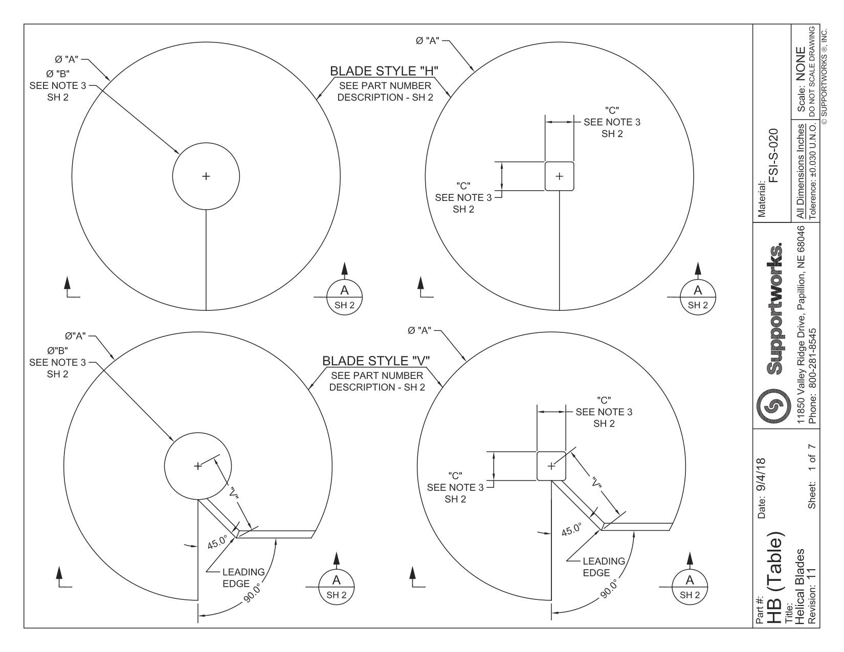
Helix Geometry: Supportworks offers two “cuts” for the helix plates. The standard H-style plate is cut to create a straight leading edge. The special order V-style plate is made with two successive 45 degree cuts to the leading edge. The V-style plate gradually engages the soil as it is rotated into the ground. This geometry allows the pile to advance into dense or rocky soils more easily. The leading edges of all helix plates are beveled at a 45 degree angle.
| Shaft Type | Net Helix Plate Area (ft2) | |||||||||||
|---|---|---|---|---|---|---|---|---|---|---|---|---|
| 6-Inch | 8-Inch | 10-Inch | 12-Inch | 14-Inch | 16-Inch | |||||||
| H | V | H | V | H | V | H | V | H | V | H | V | |
| HA150 | 0.18 | 0.16 | 0.33 | 0.30 | 0.53 | 0.47 | 0.77 | 0.68 | 1.05 | 0.92 | 1.38 | 1.20 |
| HA175 | 0.18 | 0.16 | 0.33 | 0.29 | 0.52 | 0.46 | 0.76 | 0.67 | 1.05 | 0.92 | 1.38 | 1.20 |
| HP237 | 0.17 | 0.15 | 0.32 | 0.29 | 0.51 | 0.46 | 0.75 | 0.67 | 1.04 | 0.92 | 1.37 | 1.20 |
| HP287 HP288 |
0.15 | 0.14 | 0.30 | 0.28 | 0.50 | 0.45 | 0.74 | 0.66 | 1.02 | 0.91 | 1.35 | 1.19 |
| HP350 | 0.13 | 0.12 | 0.28 | 0.26 | 0.48 | 0.43 | 0.72 | 0.65 | 1.00 | 0.89 | 1.33 | 1.18 |
| HP450 | NA | NA | 0.24 | 0.22 | 0.43 | 0.40 | 0.67 | 0.62 | 0.96 | 0.87 | 1.28 | 1.15 |
© 2016 Supportworks®, Inc. All rights reserved.